How to make your own raphnet N64 to USB (v3) adapter
Update (2022-10-29): simplified instructions, teensy section, update prices
Update (2021-07-15): removed mention of pullup resistor (internal pullup is sufficient), added mention of screw terminal shields, minor edits
Introduction
The original raphnet adapter code is designed to run on a custom board based on ATmega32U2. However, a pull request with minor changes made it so it’s possible to compile the code for an ATmega32U4, which is commonplace in many cheap development boards, such as Arduino Leonardo or Pro Micro. This guide will cover the compilation process and hardware setup necessary to turn your board into a fully functional N64 adapter.
Prerequisites
- ATmega32U4 based board clocked at 16MHz and with a 3.3V regulator, e.g. Arduino Leonardo (clones go for as low as $6). This tutorial is specifically aimed at a Leonardo clone, but it should be applicable with little or no difference to other boards that fit the criteria
- N64 extension cord ($3)
- A way to connect the wires to the board, I suggest using a soldering iron, though there are other options (e.g. screw terminal shields)
Compiling and uploading the firmware on Windows
- Download and install WinAVR with default settings (you may want to uncheck the installation of “Programmer’s Notepad”) https://sourceforge.net/projects/winavr/files/latest/download
- Download the repository with adapter’s code https://github.com/raphnet/gc_n64_usb-v3/archive/master.zip
- Extract the archive and open the resulting folder
- Open command prompt (or Powershell) in the folder and type
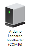
make -f Makefile.32u4. If everything before has been set up correctly, this should start the build process. A file named gcn64usb.hex should appear in the folder. - Open the Devices and Printers window and plug in your Arduino into the computer. Enter the bootloader mode on your Arduino (supposedly pressing reset once is enough on original boards, but my Leonardo clone required a double press). A device such as this should appear in the window. Memorize or write down the COM port number, as it will be required in the next step.
- Open the previous command prompt window and type in this command:
avrdude -v -p atmega32u4 -P comX -c avr109 -b 115200 -U "flash:w:gcn64usb.hex:i"Replace the “X” with your COM port number, enter the bootloader mode again and run the command. If done correctly, the code should start uploading. - Optionally, you might want to download the raphnet adapter manager and verify that the firmware on the board is indeed functional.
Preparing the hardware
Note: this section assumes basic familiarity with electronics and/or soldering. I won’t go into a great detail about how to do everything.
The circuit is very simple. Connect the N64 data line to the pin 3 on the Arduino, 3v3 line to the 3v3 pin and ground to the GND pin.
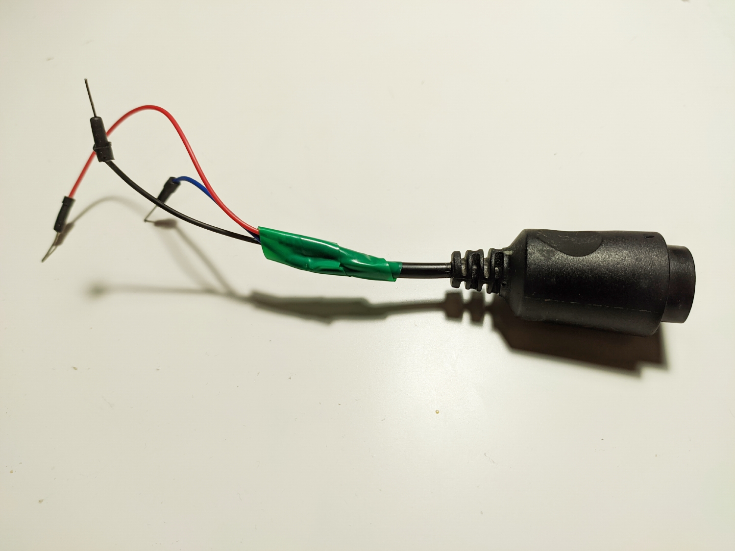
For connecting the extension cord, you may want to attach pin connectors to the cables by either bastardizing and soldering your breadboard wires (like I did) or crimping new pin connectors onto them. You may also want to simply solder the wires directly to the board instead. My modified cord as an example:
Due to huge popularity of Arduino boards, there’s also an elegant, solderless option: there are commonly available shields with screw terminals, which allow to attach the wires by simply screwing them on. You can find various types of those by searching for a phrase such as “arduino uno screw shield” - though Uno is a completely different board from Leonardo, they have the exact same pinout. Due to simplicity of the circuit, this should be a great option for people who don’t want to or cannot solder.
Additional notes
Pro Micro and other boards without a 3v3 regulator
If you decide to use a board without a 3.3V regulator (for example 5V/16MHz Pro Micro, you will have to supply the 3 volts from somewhere else. However, a quick research suggests that by making a solder bridge on J1 you can bypass the internal voltage regulator on a Pro Micro, which in case of a 3.3V board will make it run at 5V from USB. This, together with desoldering the original 8MHz oscillator and replacing it with a 16MHz one would allow to run the code without any external components (if size of the board is a concern). However, this is beyond the scope of this guide.
Adding GC functionality
Although not covered in this guide, it should be pretty straightforward. Data/3v3/ground connections stay the same, but you must also supply 5 volts for the GC controller.
Personalities and dual-port mode
It’s possible to configure the personality (displayed name) of the adapter, so e.g. if you have built an N64 only adapter it will display as “N64 to USB” instead of “GC/N64 to USB”. It’s also possible to enable dual port mode. The process is explained on raphnet’s page: https://www.raphnet.net/electronique/gcn64_usb_adapter_gen3/index_en.php#9
The pin used for 2nd controller’s data line is not documented on the page though, but my assumption is that it would be the pin 1 on Multiuse PCB-X, which equals to pin 0 on the Arduino.
Teensy++ 2.0 setup
If you have an unused Teensy++ 2.0 laying around for some undiscernible reason (omg so me), it’s possible to use it as well. Simply copy the Makefile.stk525 file and replace the CPU=at90usb1287 line with CPU=at90usb1286, then run make while specifying your edited file with -f. You can flash the resulting .hex file using the Teensy Loader: https://www.pjrc.com/teensy/loader_win10.html
It’s very important to note that the Teensy does not have a 3.3v regulator onboard, meaning its IMPOSSIBLE to safely power the controller without additional hardware.